KV-27V40 RGB Mod + SCART - 02/18/2022
Most of the consoles that interest me are from the 80s and 90s. Because of this, they are restricted to analog outputs. In most cases the console outputs RF or Composite. In other cases, you might get an s-video output. In rare cases (sega genesis & SNES) you get native RGB out. RGB is generally considered the cleanest analog video signal you can get when dealing with consoles of this vintage. Because of this, I wanted a TV that supported RGB in natively. Unfortunately, RGB in is a very rare input option for TVs in the states, so I was forced to get creative.
Shmups' TV RGB mod thread ended up being my go-to source for research and after hours of reading I finally felt comfortable proceeding with the conversion. I began my search and within a month or two I found a 27" Trinitron KV-27V40 that was a great candidate for RGB modding.
What I ended up with was a 27" TV that now included a SCART port, and a blanking switch. To use the SCART port requires that I plug in a SCART source and latch the blanking switch. To revert the TV back to using regular composite inputs, I simply unlatch the blanking switch and plug in my composite source.
All of the resistors in the pics / schematic were generated using MarkOZLAD & Syntax's OSD Mux RGB Mod Circuit v2 excel sheet / value calculator
The blanking circuit was based off of work done by tysonwarrior2
*Note - If you're in the market for RGB'ing your KV-XXV40 TV and you're using the S-video Luma input for your sync signal, you must activate the s-video plug which means it's plug sensing contact must close. This can be done by hardwire / shorting the switch, wiring it up to an external switch, or plugging in a dummy plug / full blown s-video cable. The same note applies to the Right audio channel plug. If you don't address the plug sensing contact, you'll only feed mono / Left channel audio in and it will be played through both speakers. This is all covered in the diagrams above, I just wanted to emphasize what's going on for clarity.
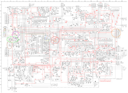
The colored circles correlate to areas of interest on my updated schematic which I will link below due to it being uploaded in high resolution:
KV-27V40 RGB SCART Schematic
Parts:
Resistors used in my application were 5.6kΩ, 1kΩ, and 75Ω.
The diodes used for my application are both 1N4148 diodes.
SCART Connector
Switch
Ribbon
More Pics + Results:


