Backup Cam + Remote 12V + Speakers - 08/23/2022
The backup cam turned out to be a small nightmare but I'm hopeful it will be worth it.
The first problem I dealt with was misunderstanding that the little transition piece on my e39 specific backup camera wasn't important. I thought I'd be clever, and lose the RCA connectors to opt for a straight hardwire to the next junction in the trunk while simultaneously bypassing the transition piece. Turns out that was a mistake:
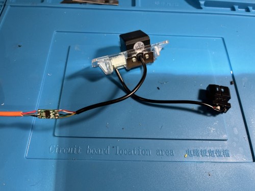
I cut the wire on the camera side of the 'transition piece' then checked the wiring to see what's what. To my surprise there were 5 wires on the camera side. Doing the math. The RCAs only need a max of 4 wires / conductors (three if they share a ground...(which I found out later they do)), so I wasn't sure what was going on. I toned it out and only one of the 5 didn't tone to the RCAs. I just thought it was an extra wire and was going to move on. Before I buttoned everything down though, I decided to tear open the transition piece, and found out I was wrong... The piece had a little PCB that took 3 wires from the RCAs, 12V, GND, and Video and converted it to 5. One 12V, Two Grounds, One 3.3V, and One Video. The 3.3V was the wire I couldn't figure out from toning.
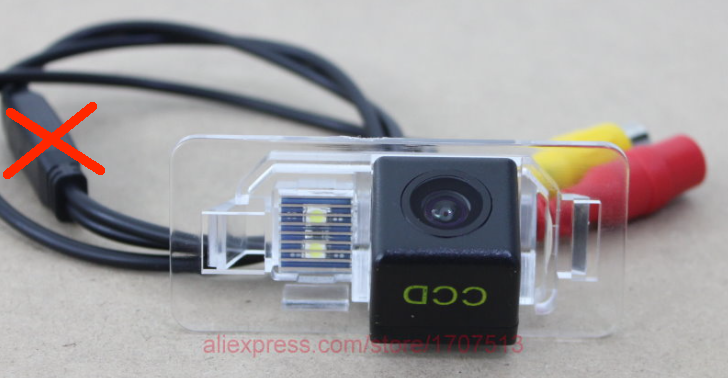
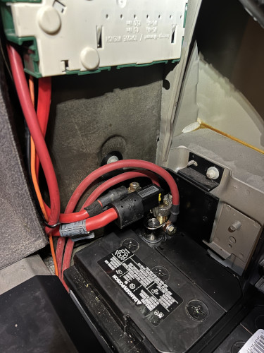
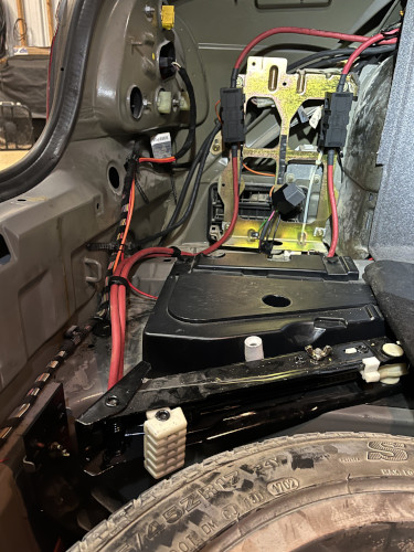
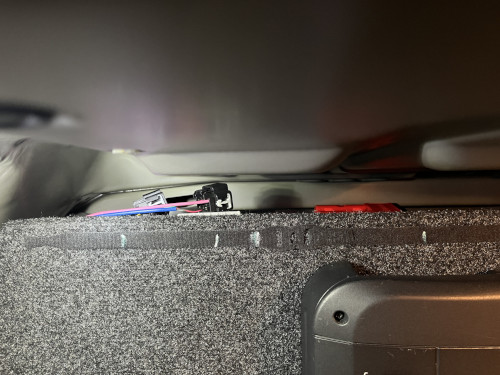
Everything turned out ok in the end. I re-installed the voltage splitter / buck step down pcb and shrink wrapped it. I also cannibalized the factory connector that was part of the stock licensee plate festoon bulb holder and made it the license plate LED portion of the backup camera plug and play. In the screenshots below, you can see the OG camera setup, the modified version with the exposed PCB (prior to shrink wrapping + the factory connector, and then the routing the new orange multiconductor from the passenger side (after getting through the trunk lid wire accordion) to the drivers side to tap into the driver's reverse light + transition to a red multiconductor. Feel free to follow along with the diagram.
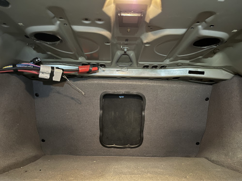
The remote 12V wasn't nearly as troublesome. This is basically an amplified remote 12v signal from the headunit used as primary power for the minidsp + remote turn ons for the amps. The headunit remote wire is used to activate the relay coil. The relay contacts are fused for 5amps. Finally, I have a bypass switch that I can use to manually turn everything on from the trunk when testing / tuning as I anticipate it will be a month or two before I get my headunit. The relay + fuse mounting is just temporary and I plan on having a finished display board in this location when I'm done.
I also wired the factory speakers to a quick disconnect offset with the power disconnects.
